ROTOR DYNAMIC STUDIES
BUMP TEST (IMPACT TEST)
The Bump Test or Impact Test, is a method for analysing the structural modal response of a machine or structure. When impacted, a machine or structure produces a broad frequency band of excitation components. When these frequency components coincide with the structural natural frequencies, then resonant conditions are present and any vibration present at or near this frequency region will be getting amplified.
During the bump test, the vibration amplitudes and frequencies are sensed with any vibration transducer such as an accelerometer and measured by frequency analysers that display plots of amplitude versus frequency. The peak amplitudes correspond to the structural flexible modes and the narrowness of the peaks provides insight as to the damaging amplification factors. In short the bump test is a rapid measure of the response characteristics of the system to either transient or rotational forces.
MODAL ANALYSIS
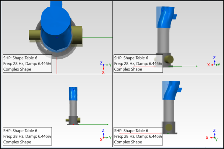
Modes (or resonances) are inherent properties of a structure. Modes change only when there is a change in the properties of the material like mass, stiffness etc. Each mode is defined by its resonant frequency, damping, and mode shape. At or near a resonant frequency, the ODS of a structure is usually dominated by a mode. A mode shape identifies the ‘potential resonance’ points in a structure or machine.
Modal analysis is the process of determining the inherent dynamic characteristics of a system in forms of natural frequencies, damping factors and mode shapes, and using them to formulate a mathematical model for its dynamic behaviour.
Modal testing is usually performed using an Instrumented Impact hammer or Shaker in which the energy is supplied to the system with a known frequency content. When structural resonances occur, there will be an amplification of the response, clearly seen in the response spectra. Using the response spectra and force spectra, a Transfer Function can be obtained. The transfer function, Frequency Response Function (FRF), is often curve fitted to estimate the modal parameters.
OPERATION DEFLECTION SHAPE (ODS)
An Operating Deflection Shape (ODS) is the deflection of a structure at a particular frequency or a band of frequencies. When motion of two or more points is specified, a shape is generated. The ODS shows where the vibration values are very highest at a particular frequency.
ODS describes
- How much the machine moves?
- Where is it moving?
- How much is one point moving with respect to another?
An ODS is the simplest way to visualize the behaviour of a machine in motion. The shapes describe the response due to internal as well as external excitations.
There are four main types of ODS analysis:
- Time ODS
- Frequency or Spectral ODS
- Running Modes ODS
- Running Orders ODS