Alignment Systems
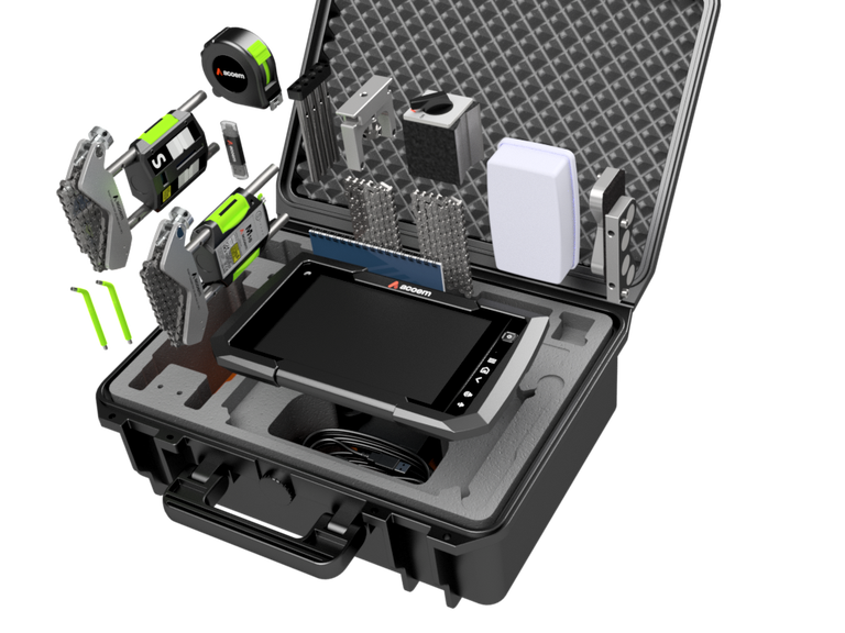
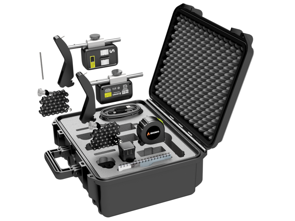
AT-400
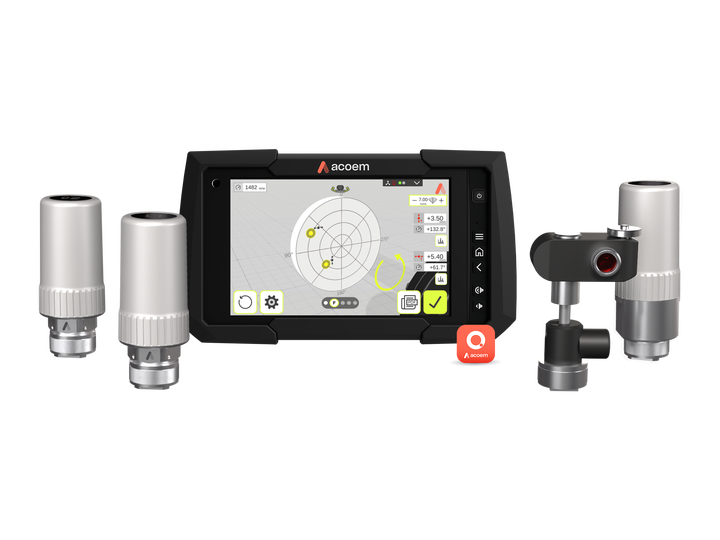
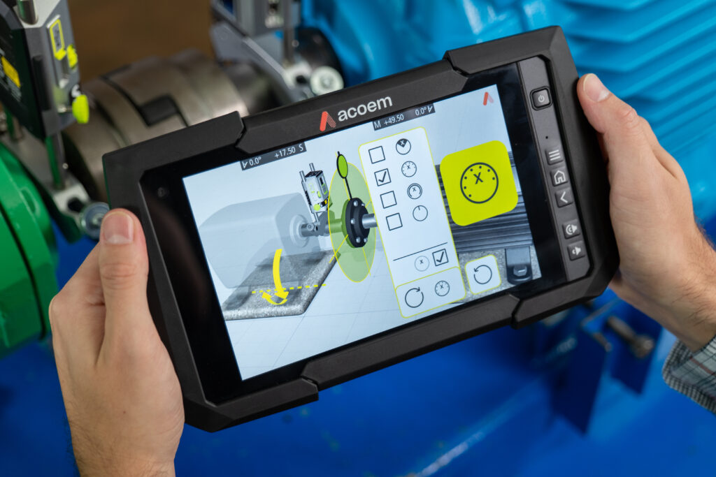
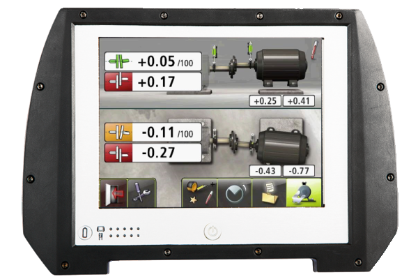
Achieve precision with the Acoem AT-400 high-end dual-axis shaft alignment system.
Its Dual Sweep method captures accurate measurements during shaft rotation, ensuring optimal alignment. Benefit from Dual Multipoint for diverse scenarios, capturing multiple points for precise calculations. Cloud connectivity streamlines report sharing, while the lifetime warranty underscores its reliability.
Trust the Acoem AT-400 for robust dual-axis sensors and unparalleled versatility. Explore various measurement programs for horizontal, vertical, flatness, and soft foot conditions.
Optimal Performance and Precision: The Two-Axis Shaft Alignment Advantage
Two-axis shaft alignment is typically the best alternative in scenarios where precision alignment in both the horizontal and vertical planes is critical to ensure the optimal performance, reliability, and safety of rotating machinery. Here are some scenarios where two-axis shaft alignment is the preferred choice:
- Complex Machinery: Machinery with multiple shafts, couplings, and components that require alignment in both horizontal and vertical directions benefit from two-axis shaft alignment. This includes systems with multiple gearboxes, pumps, or interconnected rotating elements.
- Critical Applications: Industries with critical applications such as aerospace, automotive manufacturing, and medical device production often require the highest level of precision in alignment. Two-axis alignment ensures that the machinery operates with extreme accuracy.
- Heavy Machinery: Large and heavy machinery used in construction, mining, or marine applications often require two-axis alignment to ensure stability and prevent misalignment-related failures.
Key Features of GuideU™ Interface:
- Customization: GuideU™ empowers users with a patented customization system. Tailor the interface to your specific needs and preferences, ensuring a seamless alignment experience every time.
- Icon-Driven Design: Our innovative icon-driven design transforms complex alignment tasks into intuitive actions. Easily navigate through the alignment process, regardless of your expertise level.
- Color-Coded Display: Visual clarity is paramount in shaft alignment. GuideU™ employs a sophisticated color-coded display system that enhances differentiation and understanding, promoting error-free alignment.
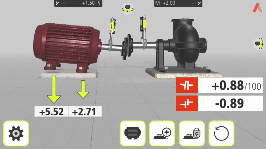
- Realistic Machine Graphics: Immerse yourself in true-to-life machine graphics that simulate real-world conditions. Gain a comprehensive understanding of alignment requirements without the need for guesswork.
- Animated Help Screens: Eliminate uncertainty with animated help screens that guide you through each step of the alignment process. Minimize the risk of human error and increase alignment accuracy.
Acoem Cloud – Seamless Cloud Connectivity
With the help of cloud connectivity, the Acoem AT-400 makes it easy for users to send alignment reports to Acoem’s special website. This keeps data organized and lets you access alignment records for checking and comparing whenever you need. Just by tapping a button, technicians can quickly send their alignment reports straight to the website, making their documentation process super smooth.
Dual precision at every turn: measuring methods for industry leaders
Discover precision like never before with our advanced measuring methods. Engineered to perfection, these techniques redefine accuracy in industrial alignment assessments.
- Dual Sweep Method: Automated alignment evaluation for coupled machines, ensuring precision with every sweep. Take control by stopping data recording manually.
- Dual Sweep Express Method: Effortless efficiency – data recording halts automatically when shaft rotation stops, streamlining the process.
- Dual Multipoint Method: Unparalleled flexibility. Start measurements from any position, ideal for uncoupled shafts and non-rotatable machinery.
- Dual Multipoint Express Method: Convenience meets accuracy. Automated measurements without compromise.
- Tripoint Method: Meticulous precision. Record three manual points during shaft rotation for detailed alignment insights.
- Tripoint Express Method: Seamlessly automated. Experience precision alignment assessment with automated ease.
- Clock Method: Industrial wisdom in action. Three points, 180° rotation – a trusted technique for non-horizontal foundations and standalone shafts.
At ACOEM, we redefine measurements for industry excellence. Elevate your operations with unmatched precision.
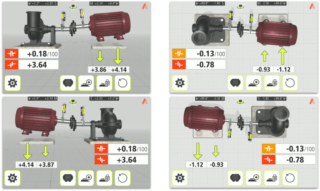
GuideU™ Interface: revolutionizing 3D shaft alignment
Experience GuideU™ – the innovative 3D shaft alignment interface. With patented customization, intuitive icons, and vivid colors, measuring, aligning, and reporting become effortless.
Minimize human error and uncertainty in shaft alignment through realistic graphics and animated help screens. GuideU™ Interface represents a groundbreaking leap in 3D shaft alignment technology. Our proprietary and patented graphical user interface redefines precision, simplicity, and accuracy in the alignment process.
Lifetime Warranty – Your Product, Our Commitment, Forever!
Experience the unparalleled advantage of a lifetime warranty with the ACOEM AT-400. Our commitment extends beyond just a product, offering customers exceptional tranquility and enduring dependability. This dedication to excellence mirrors Acoem’s unwavering belief in the robustness and proficiency of this state-of-the-art shaft alignment system.

- Review of maintenance practices
- Review of condition monitoring technologies
- Principles of vibration
- Data acquisition
- Proximity probes
AT-300
Next-generation digital line laser system redefining precision and productivity in measuring methods.
Welcome to the future of laser measurement technology with the Acoem AT-300, the next-generation digital line laser system engineered for exceptional performance. With extensive software functionality, a streamlined user interface, and intelligent sensor technology, the Acoem AT-300 is designed to revolutionize your experience across various applications.
At the heart of the Acoem AT-300 lies a commitment to excellence in various measuring methods. Our cutting-edge technology ensures swift and accurate results, enhancing both performance and precision. Say goodbye to guesswork and hello to precise measurements every time.
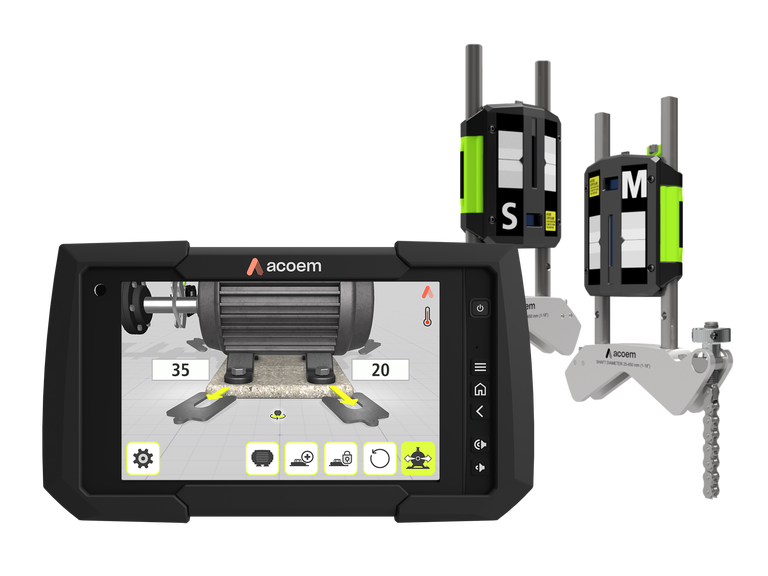
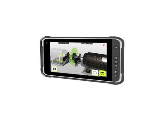
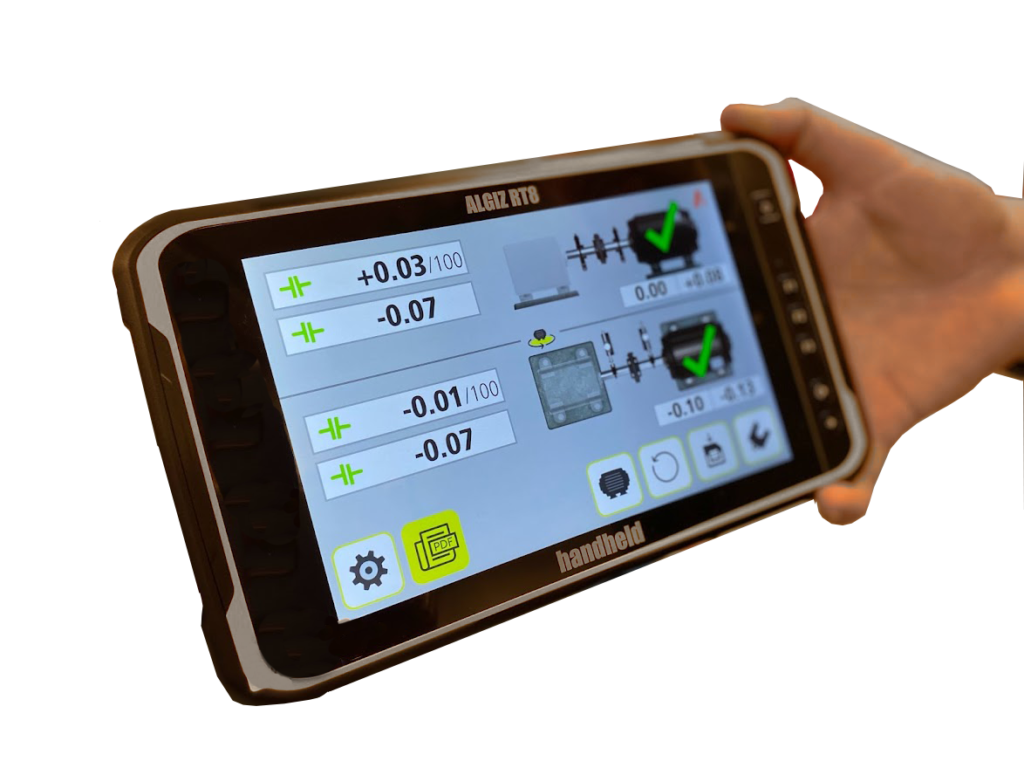
ACOEM Alignment Display: unparalleled sunlight readability and rugged performance
When it comes to industrial displays, you need a device that can stand up to the harshest conditions while providing exceptional performance. The ACOEM Alignment Display is the answer to your rugged display needs. With a range of features designed to excel in tough environments, this 8-inch capacitive multi-touch display is a game-changer in the industry.
- Sunlight-Readable: Enjoy clear visibility in bright conditions with Gorilla Glass.
- Rugged Performance: IP67 rating ensures waterproof and dust-tight operation.
- Extreme Temperatures: Operates flawlessly from -20°C to 60°C (-4°F to 140°F).
Upgrade to the ACOEM Alignment Display for reliability in any environment.
Measurement Methods
- Clock™ Method: Machinery positions are calculated using three points with a 180° rotation.
- TRIPOINT Express™ Method: This method seamlessly incorporates the Tripoint approach, offering the advantage of fully automated measurements throughout the process.
- Tripoint™ Method: Alignment conditions are calculated by taking three points while rotating the shaft at least 60°, with all points taken manually.
Multipoint Method: This function enables measurement initiation from any position on the rotation, allowing recording of multiple points for optimized calculations. Ideal for turbine and sliding bearing applications. - Multipoint Express Method: Our method follows the classic Multipoint method approach, but with the advantage of automated measurements for greater convenience
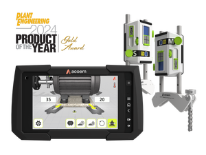
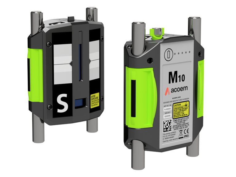
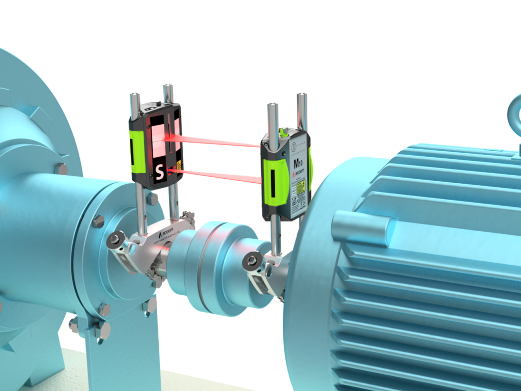
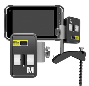
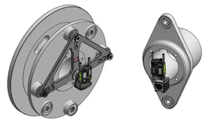
Introducing the next generation of sensors: Acoem M10/S10
Revolutionize your data acquisition processes with our state-of-the-art M10/S10 sensors. These third-generation sensors are set to redefine the industry standards with their optimized power usage and an expanded measurement range that goes beyond expectations. Get ready to unlock unparalleled capabilities in data collection, all thanks to our cutting-edge, high-performance technology.
- Enhanced Performance: At the heart of the Acoem M10/S10 sensors lies a commitment to delivering exceptional performance. We have taken a significant leap forward in sensor technology by reducing power consumption without compromising on accuracy. With these sensors, you can expect a significant boost in efficiency and reliability in your data acquisition endeavors.
- Extended Measurement Range: The Acoem M10/S10 sensors boast a remarkable 15-meter measurement range, making them perfect for applications where accurate distance detection is crucial. Whether you’re monitoring industrial processes, automating machinery, or ensuring safety in your workspace, these sensors have the reach and precision you need.
- Advanced Software Capabilities: In addition to their impressive hardware features, our Acoem M10/S10 sensors now come equipped with extensive software capabilities. This means you can fine-tune your data acquisition processes to meet your specific requirements.
- Versatile Applications: Our Acoem M10/S10 sensors are designed to excel in a wide range of industries and applications, these sensors provide the accuracy, reliability, and flexibility needed to tackle any task. You can count on them to deliver consistent, high-quality data, no matter the
environment.
Advanced software functionality and user-friendly interface
Boost your productivity and efficiency with the extensive software functionality of the AT-300. Whether you need comprehensive assistance, real-time interaction, support, or detailed PDF reports, the AT-300 has you covered. Our commitment to innovation means you’ll always have access to the latest tools and features to stay ahead in your field.
- Review of maintenance practices
- Review of condition monitoring technologies
- Principles of vibration
- Data acquisition
- Proximity probes
AT-200
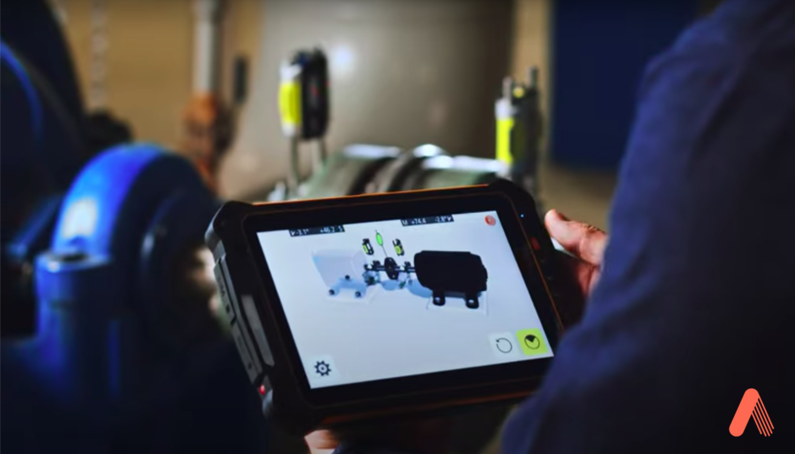
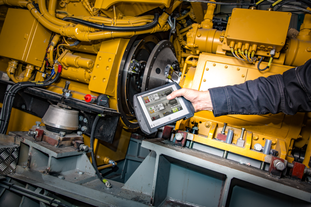
The smart app-based shaft alignment solution
This new generation of horizontal & vertical laser shaft alignment solution is the result of almost 40 years of expertise and innovation.
Integrated apps, customized technology features and easy connectivity : the AT-200 leverages technology to enhance your user experience and improve the efficiency of your maintenance teams. Providing unparalleled measurement performance and fast, precision alignment, the AT-200 improve measurement and reporting capabilities, to help you extend every critical machinery’s lifespan.
Improve your maintenance team’s efficiency
The AT-200 improves the user experience of your shaft alignment operations, offering :
- Accessibility and efficiency : wireless, easy to implement, user friendly new technology tools
- Time saving and reliability : quick and easy verification of pre-alignment steps, accelerated handling on standard mobile devices (Free laser App for IOS and Android Devices)
- Fewer errors: optimal visual guidance
- An accelerated decision-making process : instant reporting
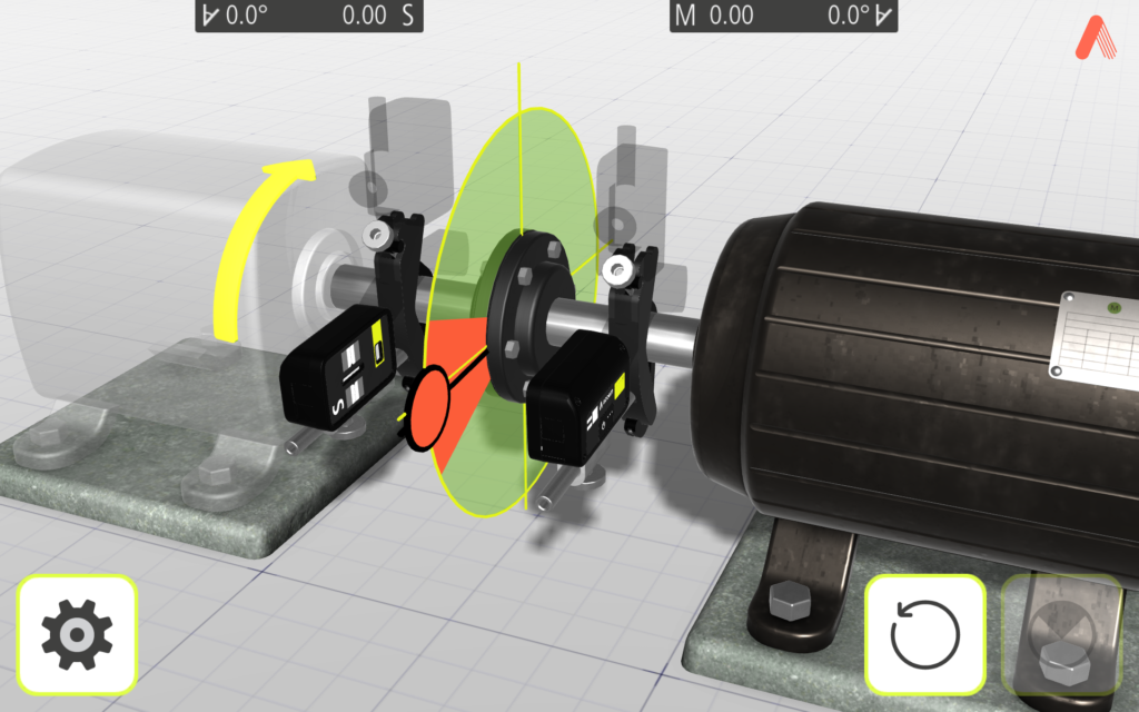
GuideU™- Intuitive 3D graphical user interface
GuideU™ is the next generation alignment 3D graphical user interface – our patented, customisable, icon-driven and color-coded display system makes measuring, aligning, documenting and reporting on each job simple.
GuideU™ delivers precise measurement, 3-D transitions in alignment view and correction values by minimising the risk of human errors, guiding the operator through the process using visual, logical and easy-to-follow steps.
Alignment intelligence : the best accuracy for industrial applications
The supervisor CCD technology of AT-200 sensors makes them highly tolerant of detrimental external factors, such as vibration and ambient light and provides unrivalled digital filtering capabilities. Simply switch ON the smart Alignment Intelligence filter to automatically adjust sampling time and provide intelligent screen filtering in live alignment mode with outstanding results. The line laser virtually eliminates rough alignment, delivering the most accurate and precise measurement values throughout the alignment process.
Grow your maintenance capabilities
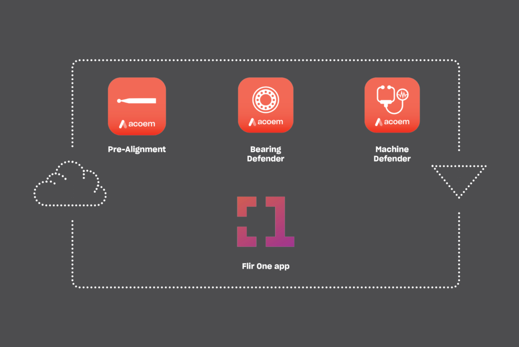
The Horizontal and Vertical shaft alignment apps are part of Acoem’s Augmented Mechanics Ecosystem, the first truly flexible and scalable solution for combining different technologies on the same mobile platform to deliver reliable and precise proactive and predictive maintenance for industrial machinery.
Designed to allow you to continually add to or upgrade as new technologies become available, or as your specific needs change over time, the Ecosystem is made up of a combination of mobile applications, connected wireless sensors.
In addition to the Horizontal and Vertical shaft alignment apps, the Ecosystem currently features:
- The Pre-alignment app, designed to remove the complexity of your laser alignment process, making it faster and more reliable (works with the Acoem wireless Run-out probe)
- The Bearing Defender app, which provides quick first-level information on bearing health based on vibration readings in a matter of seconds (works with an Acoem wireless vibration sensor)
- The Machine Defender app, which provides full rotating machinery with AI-powered vibration diagnostics instantly in the field (works with an Acoem wireless vibration sensor)
A complete shaft alignment tool
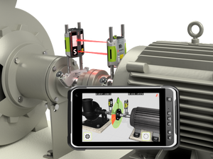
So much more than an horizontal and vertical laser shaft alignment tool, the AT-200 Toolbox gives you the power to make informed decisions and take corrective maintenance action immediately, straight from your tablet or smartphone :
- Fast and accurate results, powered by intelligent sensor technology
- Easy-of-use, via our shaft alignment apps
- Easy data sharing capabilities thanks to a full integration and connectivity system
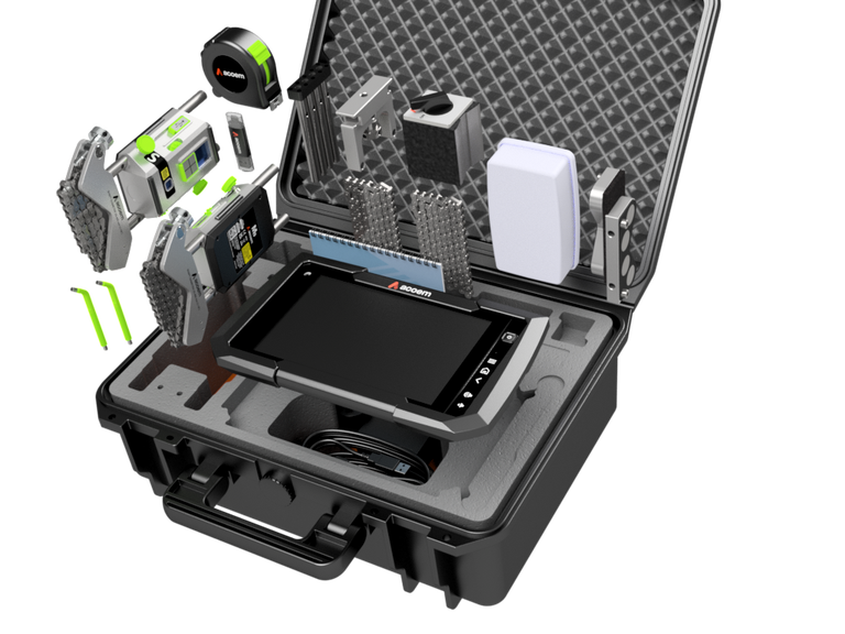
The toolbox includes:
- Two smart wireless sensors with their accessories
- Task oriented Horizontal & Vertical shaft alignment mobile apps
- Acoem Cloud connectivity with report storage, trending and work order and sharing capabilities with secure communication (optional)

Reduce downtime and improve productivity
A complete shaft alignment solution where precision alignment matters. Even the smallest angle of misalignment can drastically reduce the lifespan of rotating machinery by more than 50%. This can be avoided by proactively undertaking precision alignment as part of your maintenance program. Proper alignment practices not only help reduce downtime but also improve productivity.
- Avoid unexpected failures which can causing complete process shutdowns or safety incidents
- Eliminate the root cause of 50% of bearing failures
- Extend the lifetime of your assets and reduce the total costs of ownership
- Reduce energy consumption by up to 10%.
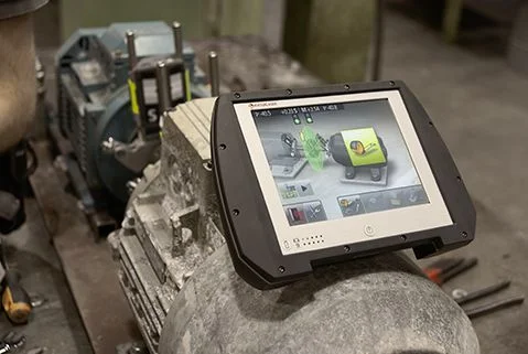
TrueLiveTM – Save time with revolutionized live shaft alignment
An industry-first technology, TrueLive™ functionality ensures that you always know your machine’s exact position. Its two compact smart sensors feature laser beams and inclinometers which monitor both shaft positions simultaneously. Even if you move the machine’s position out of detector range or interrupt the laser beam, the smart sensors will resume with an updated machine position and always deliver live values, saving you considerable time when aligning your machinery.

Reduce alignment time with adaptative user interface
VertiZontalT™ adaptive user interface automatically indicates exactly how much you need to adjust your misaligned machine by adding or removing shims to the machine’s feet. This removes the need to remeasure between the vertical and the horizontal phases to correct the horizontal misalignment. This industry-first function saves time and ensures accuracy with every measurement.
- Review of maintenance practices
- Review of condition monitoring technologies
- Principles of vibration
- Data acquisition
- Proximity probes
AT-100
An app-based solution for shaft alignment
AT-100 is an app-based alignment tool that combines integrated apps, patented technology, and easy connectivity. The AT-100 is suitable for entry-level to expert shaft alignment work, the AT-100 shaft alignment tool provides high measurement flexibility. The intuitive tool works with the shaft alignment apps on a tablet or smartphone. It is simple to use and doesn’t require any special training. The AT-100 shaft alignment solution is the result of almost 40 years of shaft alignment expertise and innovation, leveraging the latest technology to enhance your user experience.
VertiZontal™
VertiZontal™ adaptive user interfaceautomatically indicates exactly how much you need to adjust your misaligned machine by adding or removing shims to the machine’s feet. This removes the need to remeasure between the vertical and the horizontal phases to correct the horizontal misalignment. This industry-first function saves time and ensures accuracy with every measurement.
GuideU™
The next generation of 3D shaft alignment graphical user interfaces provides patented, customizable, icon-driven, and color-coded displays, making it easy to measure, align, document, and report on each job. Using visual, logical, and easy-to-follow steps, GuideU™ offers precise measurement and correction values and minimizes the risk of human errors.
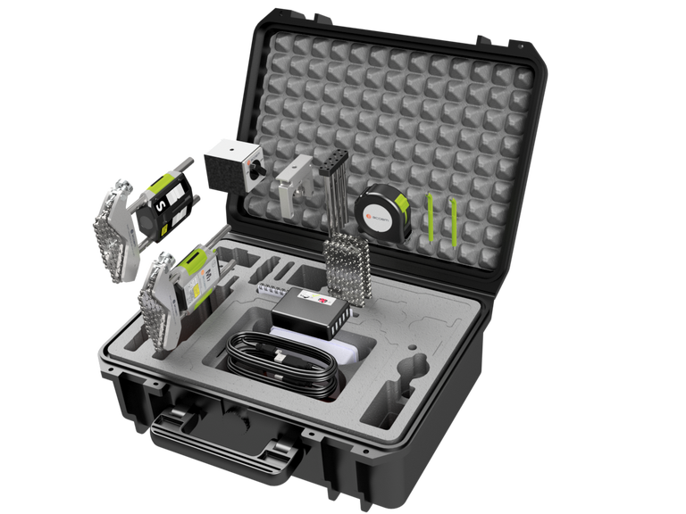
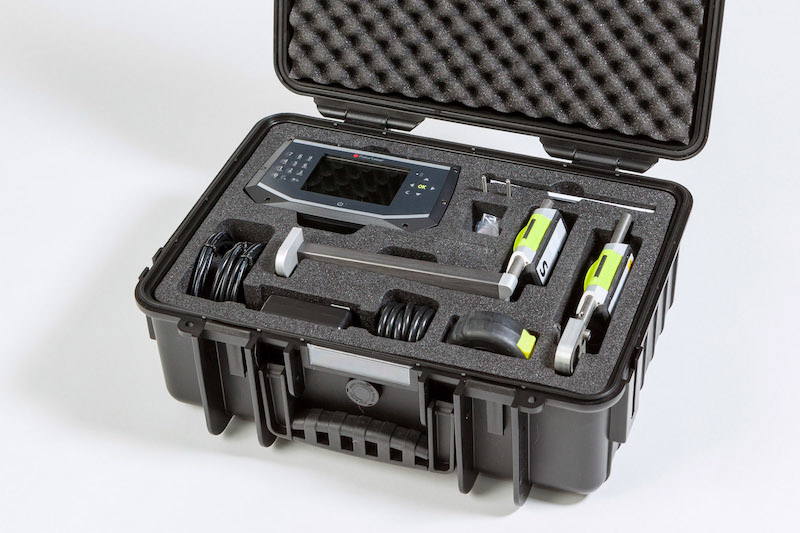
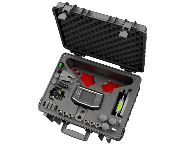
AT-100 Packaging & Deliverables
Each AT-100 is delivered with the following package:
- Sensor, M8/S8
- Rod kit NXA
- Chain 12,7 mm 60 links (L=500 mm)
- Tape measure 5 m
- V-bracket complete
- Angled universal tool – 1 pcs
- USB-cable A-mini B 2m
- Power supply 2 USB-ports 5 VDC
- Review of maintenance practices
- Review of condition monitoring technologies
- Principles of vibration
- Data acquisition
- Proximity probes
ECO Mitsubishi
What’s Included
- ECO Display Unit with 4” Color LCD Screen
- Custom-made fixtures for Mitsubishi turbines
- Moveable machine transmitter/detector with 20 mm CCD sensor
- Stationary machine transmitter/detector with 20 mm CCD sensor
- Rod tools (2)
- Tape measure (5m)
- USB Cable A-micro B (.5m)
- USB Cable A-micro B (1.5m)
- Power Cable US (2m)
- Carrying case – IP-65, high impact ABS
- Manuals – ECO (printed and CD)
- Lifetime warranty standard

Horizontal Machines
The NXA Ultimate is perfect for measuring horizontal alignment conditions but its real power is in helping correct misalignment. The dual sensors allow the NXA to maintain the true position of the shafts, even as unintended movements are experienced during the alignment process. The benefit of this “true positon sensing” is that it allows the user to complete the alignment using the Verti-Zontal™ compound move, adjusting in both the vertical and horizontal planes without remeasuring between moves. A Verti-Zontal™ alignment is a great time saver since alignments can be completed in just one or two tries. The NXA Ultimate also comes with a number of utility programs to make the alignment process easier. These include Softcheck™ to control for soft foot conditions, FeetLock™ to deal with base and bolt bound situations, HotCheck™ to calculate the difference between measurements taken in a cold state versus a hot condition, and Target Values, which automatically adjusts the readings to compensate for pre-determined alignment targets based on thermal growth or dynamic movement data.
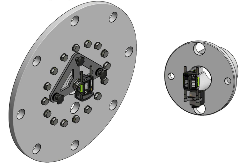
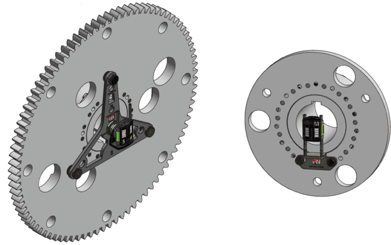
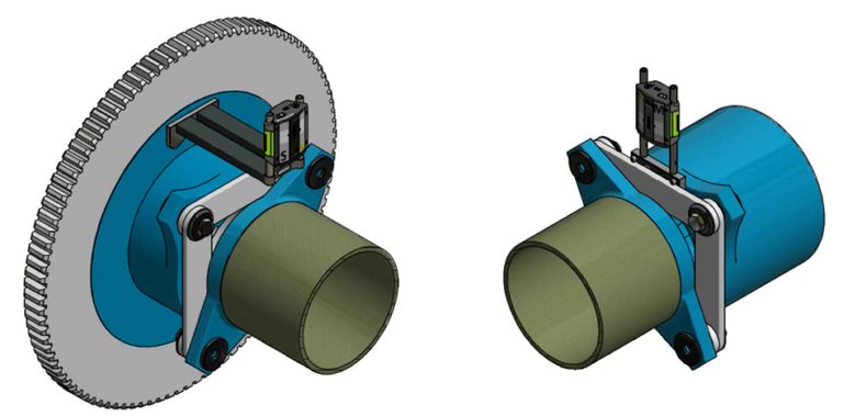
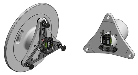
Make generator-to-gearbox alignment inside any nacelle easy!
Acoem shaft alignment instruments are custom made with firmware features that ensure high measurement accuracy and with mounting hardware that is ideally suited for optimal alignment of the gearbox and generator shafts in wind turbines. No matter the manufacturer, coupling or turbine type, Acoem’s shaft alignment instruments make generator-to-gearbox alignment inside any nacelle easy. This safeguards reliability and optimizes the energy efficiency of the wind turbine.
- Review of maintenance practices
- Review of condition monitoring technologies
- Principles of vibration
- Data acquisition
- Proximity probes
ECO GE
Shaft alignment in the wind power Industry
The ECO GE is custom-made with firmware and fixtures designed specifically for GE 1.5x and 2.5x. These precisely designed fixtures make generator-to-gearbox alignment easy inside any nacelle – safeguarding reliability and optimizing the energy efficiency of the wind turbine.
Make generator-to-gearbox alignment inside any nacelle easy !
Acoem shaft alignment instruments are custom made with firmware features that ensure high measurement accuracy and with mounting hardware that is ideally suited for optimal alignment of the gearbox and generator shafts in wind turbines. No matter the manufacturer, coupling or turbine type, Acoem’s shaft alignment instruments make generator-to-gearbox alignment inside any nacelle easy. This safeguards reliability and optimizes the energy efficiency of the wind turbine.
What’s Included
- ECO Display Unit with 4” Color LCD Screen
- Custom-made fixtures for GE turbines
- Moveable machine transmitter/detector with 20 mm CCD sensor
- Stationary machine transmitter/detector with 20 mm CCD sensor
- Rod tools (2)
- Tape measure (5m)
- USB Cable A-micro B (.5m)
- USB Cable A-micro B (1.5m)
- Power Cable US (2m)
- Carrying case – IP-65, high impact ABS
- Manuals – ECO (printed and CD)
- Lifetime warranty standard

- Review of maintenance practices
- Review of condition monitoring technologies
- Principles of vibration
- Data acquisition
- Proximity probes
NXA GAMESA
The NXA GAMESA is custom-made with firmware and fixtures designed specifically for Gamesa turbines: G80x, G90x, G114, G126, G132, G145. These precisely designed fixtures make generator-to-gearbox alignment easy inside any nacelle – safeguarding reliability and optimizing the energy efficiency of the wind turbine.
Machine Train
The NXA Pro’s machine train routine simplifies the complexity of aligning multiple units with connecting shafts. The software includes a “minimal moves” function which identifies the best reference machine to minimize the number of moves required to complete the alignment.

What’s Included
- Full VGA 6.5″ color display, TFT-LCD backlit, sunlight readable, with wide angle viewing technology
- M3 moveable machine transmitter/detector with 30mm CCD sensor and built-in Bluetooth II
- S3 stationary machine transmitter/detector with 30mm CCD sensor and built-in Bluetooth II
- Custom-made fixtures for Gamesa turbines
- Rod extension kit
- NXA extension fixture
- Angled Universal Rod tools (2)
- Magnetic base for mounting on large diameter shafts
- External power supply NXA built into carrying case
- Carrying case – IP-65, high impact ABS
- NXA tape measure
- USB stick
- Manuals – NXA
- Lifetime warranty standard
Horizontal Machines
The Acoem NXA Pro is perfect for measuring horizontal alignment conditions but its real power is in helping correct misalignment. The dual sensors allow the NXA Pro to maintain the true position of the shafts, even as unintended movements are experienced during the alignment process.
Spacer Shaft
With spacer shafts there are two power planes of transmission that need to be aligned to the correct tolerances. The NXA Pro spacer shaft program simplifies the process showing both ends of the spacer shaft coupling with an angle/angle display. The alignment is completed using the Verti-Zontal™ move.
- Review of maintenance practices
- Review of condition monitoring technologies
- Principles of vibration
- Data acquisition
- Proximity probes
ECO VESTAS
Shaft alignment in the wind power Industry
The ECO VESTAS is custom-made with firmware and fixtures designed specifically for Vestas turbines.
- V1 Bracket: V44, V47, V52, V63, V66, V80, V90, V100, V110
- V2 Bracket: V105, V112, V113, V117, V120, V126, V136, V150, V164
These precisely designed fixtures make generator-to-gearbox alignment easy inside any nacelle – safeguarding reliability and optimizing the energy efficiency of the wind turbine.
What’s Included
- ECO Display Unit with 4” Color LCD Screen
- Custom-made fixtures for Vestas turbines
- Moveable machine transmitter/detector with 20 mm CCD sensor
- Stationary machine transmitter/detector with 20 mm CCD sensor
- Rod tools (2)
- Tape measure (5m)
- USB Cable A-micro B (.5m)
- USB Cable A-micro B (1.5m)
- Power Cable US (2m)
- Carrying case – IP-65, high impact ABS
- Manuals – ECO (printed and CD)
- Lifetime warranty standard
Horizontal Machines
The NXA Ultimate is perfect for measuring horizontal alignment conditions but its real power is in helping correct misalignment. The dual sensors allow the NXA to maintain the true position of the shafts, even as unintended movements are experienced during the alignment process. The benefit of this “true positon sensing” is that it allows the user to complete the alignment using the Verti-Zontal™ compound move, adjusting in both the vertical and horizontal planes without remeasuring between moves. A Verti-Zontal™ alignment is a great time saver since alignments can be completed in just one or two tries. The NXA Ultimate also comes with a number of utility programs to make the alignment process easier. These include Softcheck™ to control for soft foot conditions, FeetLock™ to deal with base and bolt bound situations, HotCheck™ to calculate the difference between measurements taken in a cold state versus a hot condition, and Target Values, which automatically adjusts the readings to compensate for pre-determined alignment targets based on thermal growth or dynamic movement data.
- Review of maintenance practices
- Review of condition monitoring technologies
- Principles of vibration
- Data acquisition
- Proximity probes
PAT
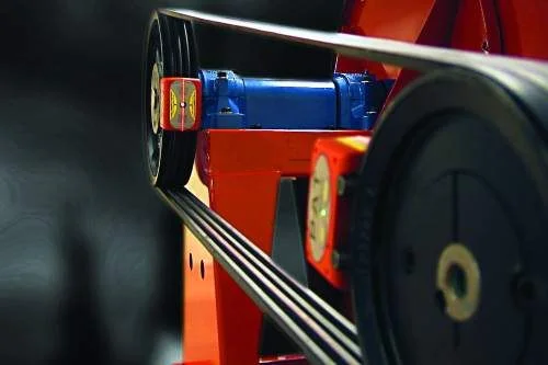
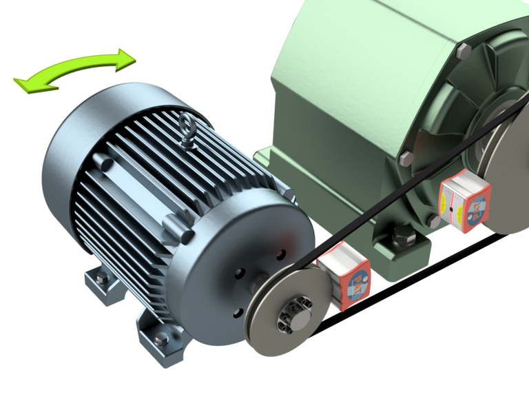
The final solution to all your belt alignment needs!
With the PAT, you are never in doubt about whether your belt transmissions are aligned or not. By using the groove as reference, you will achieve a precise alignment which reduces belt wear, bearing failures and vibrations.
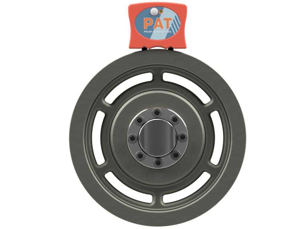
Mounting of the transmitters
The PAT units are very easily mounted on the pulleys. The spring action probe finds the center of the belt groove. The industrial built-in magnets snap the units to the pulley in a perfect fit. The PAT is equipped with various-sized removable guides to fit standard sheave sizes A-E (6 mm – 40 mm). Additional guides for the alignment of timing belts are available as accessories.
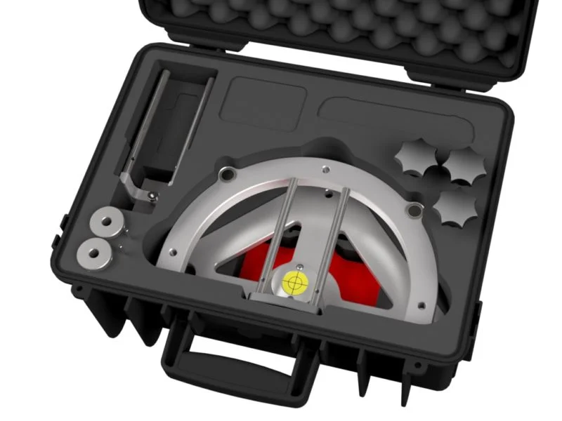
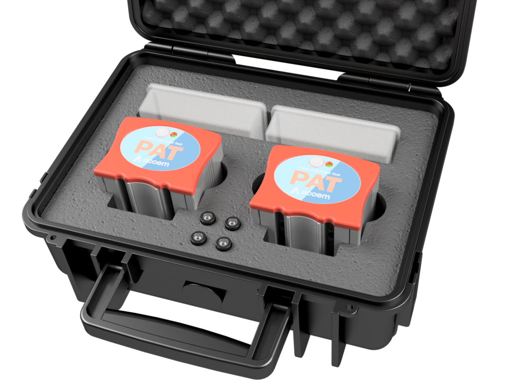
What’s in the case ?
PAT – Complete system
- 2 boxes of V-guide tips
- 1 pair of laser transmitters
- 4 batteries, LR 03 1.5V (AAA)
Two transmitters with visible red laser line
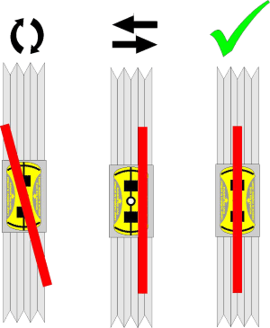
The PAT comes with two-line laser transmitters, each equipped with two spring-loaded guides that fit into the pulley grooves. The use of two laser transmitters with integrated targets makes it very easy to find out what kind of alignment is required. Parallel offset, angular error, and twist are instantly visible to the operator. Within a few minutes, the operator can determine if the machine requires alignment or not.
The alignment process with the PAT
The visible red laser line makes it easy to determine the position of your belt-driven machines.
The alignment process is as easy as the mounting. Just turn on the lasers and look at the opposite mounted unit. The laser draws a line on the target label as in the illustration to the right. If necessary, adjust your machine position until the laser lines are aligned with the center mark on both units.
- Review of maintenance practices
- Review of condition monitoring technologies
- Principles of vibration
- Data acquisition
- Proximity probes
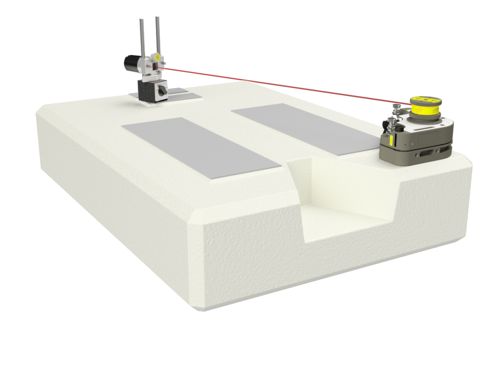
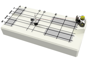
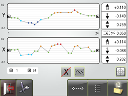
Rectangular flatness measurements
Stay square with the NXA geometry
Typical applications are measurements of e.g. machine beds and machine foundations. For the latter application, it is particularly beneficial to combine flatness measurement with shaft alignment when installing rotating machinery. First, you check the foundation’s surface for possible irregularities, a so-called pre-alignment check. If any, adjust these. Install the machine and check for possible misalignment with a laser-based shaft alignment tool like the NXA Ultimate system.
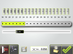
1. Configuration
- Quick and easy to configure
- Pre-defined configuration
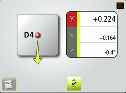
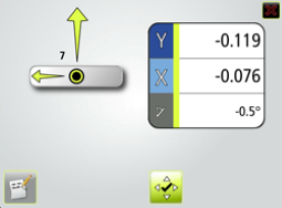
3. Adjustment
- Live values during the adjustment phase
- The angle guide displays the accepted (green) measurement point registration area
- Green arrows show you in which direction to adjust towards zero
- Color-coded measurement values
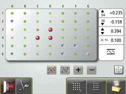
How to do a Rectangular Flatness Measurement
This application uses a laser plane as a reference. The deviation in distance between the laser plane and the measurement object is measured in one or more positions with the use of the receiver. The program allows for up to 150 points (10 x 15) to be measured.
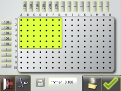
2. Measurement
- Distinct overall view of the measurement
- Instant display of measurement object’s position
- Color-coded measurement points
- Measurement points can be registered in any order you prefer
- Review of maintenance practices
- Review of condition monitoring technologies
- Principles of vibration
- Data acquisition
- Proximity probes
NXA Ultimate
With the NXA Ultimate you have covered any kind of angle that needs to be covered of your machinery. It includes shaft alignment applications as well as geometric applications, hence, as the name says, it is an ultimate measurement tool.
- Review of maintenance practices
- Review of condition monitoring technologies
- Principles of vibration
- Data acquisition
- Proximity probes
Bore measurements
Halfbore or fullbore – no bore for our instruments
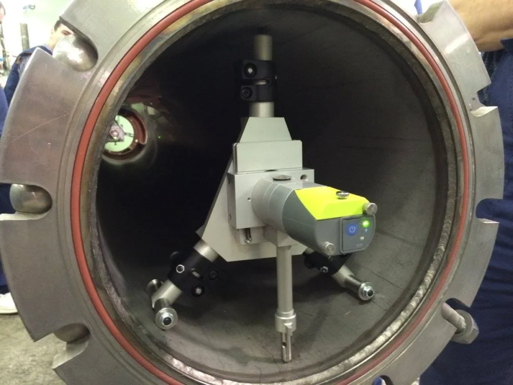
Typical applications are full bore measurements, e.g. bearing journals for compressors and in diesel engines.
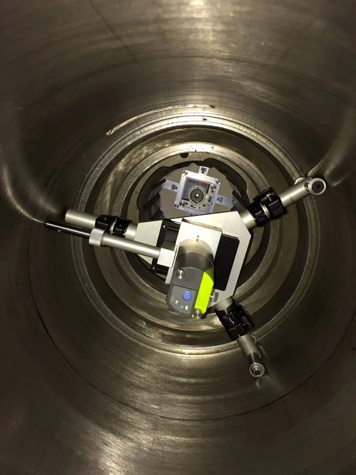
How to do a straightness measurement with the arc angle method
Typical applications are half bore measurements, e.g. compressors and turbines with split casings.
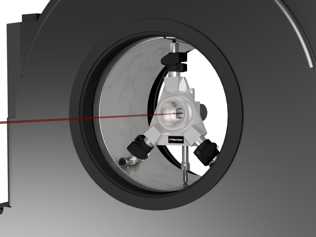
Straightness measurements with the Arc Angle method are made by setting the laser beam roughly parallel to a centerline.
Two points are used as references. The sensor is placed in three to nine positions at each measurement point to find the center of the measurement object. For the Arc Angle measurements, the detector is in a single-axes mode.
The program allows for up to 99 points to be measured.

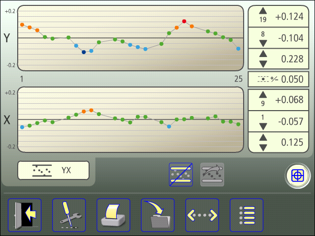
2. Measurement
- Distinct overall view of the measurement
- Instant display of measurement object’s position
- Color-coded measurement points
- Measurement points can be registered in any order you prefe


How to do a straightness measurement with the Clock Method
When measuring straightness with the clock method, you set the laser beam roughly parallel to a centerline. The center position of each bore can be measured by taking readings with the receiver in two points, 180° apart.
Two points can be used as references. The program allows for up to 99 points to be measured.
1. Configuration
- Quick and easy to configure
- Pre-defined configuration
3. Adjustment
- Live values during the adjustment phase
- The angle guide displays the accepted (green) measurement point registration area
- Green arrows show you in which direction to adjust towards zero
- Color-coded measurement values
- Review of maintenance practices
- Review of condition monitoring technologies
- Principles of vibration
- Data acquisition
- Proximity probes
Straightness measurement
Straightness with an edge
The straightness application is measured in two axes, where the laser beam is used as a reference. The deviation in distance between the laser beam and the measurement object is measured in two or more positions with the use of a receiver.
How to do a straightness measurement
1. Configuration
- Quick and easy to configure
- Pre-defined configuration
3. Adjustment
- Live values during the adjustment phase
- The angle guide displays the accepted (green) measurement point registration area
- Green arrows show you in which direction to adjust towards zero
- Color-coded measurement values
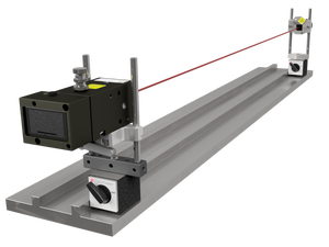
What does the program do ?
The program allows for up to 99 points to be measured.
Typical straightness applications are measurements of machine guides, machine beds, machine ways, and guide rails.
2. Measurement
- Distinct overall view of the measurement
- Instant display of measurement object’s position
- Color-coded measurement points
- Measurement points can be registered in any order you prefer
- Review of maintenance practices
- Review of condition monitoring technologies
- Principles of vibration
- Data acquisition
- Proximity probes
Bore measurements
- Review of maintenance practices
- Review of condition monitoring technologies
- Principles of vibration
- Data acquisition
- Proximity probes
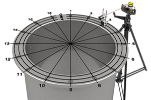
Circular flatness measurement
- Review of maintenance practices
- Review of condition monitoring technologies
- Principles of vibration
- Data acquisition
- Proximity probes